GLOSSARY
DEVELOP
Operating principle
A mechanical ventilator is a machine or equipment that helps breathing when a
patient cannot breathe in a sufficient measure by their own means. It is
used in order to bring oxygen to the lungs and to the organism, to help the
lungs to get rid of carbon dioxide. Also, to facilitate breathing: in some
cases, the patient can breathe, but it is very difficult.
For its operation, the equipment is first
connected to the patient through an endotracheal tube (ET) that is placed
inside the mouth or nose and inside the trachea. In some patients, a hole is
made in the neck by a surgical procedure and a tracheostomy tube is connected
there. The ventilator then blows gas (fresh air, as needed) into the patient's
lungs. It can handle one hundred percent of the breath or only help the
patient's breathing.
The ventilator can deliver higher oxygen
levels than a mask or other types of device. It may also offer a pressure (PEP
pressure) that helps keep the lungs open so that the pulmonary alveoli do not
collapse. The tube in the trachea makes it easier to remove mucus in case of a
mild cough.
The differences between the different types of ventilation:
Some ventilation modes are:
CPAP (Continuous Positive Airway Pressure): It is a continuous spontaneous ventilatory mode in inspiration and exhalation, applied by means of positive pressure systems, mechanical and non-mechanical. Its fundamental parameters are:
- Pressure
- flow
- Others: oxygen / additional medical air, humidification systems
BIAPAP (Bilevel Positive Airway Pressure): This ventilated mode enhances the patient's inspiration. For the inspiratory aid, the trigger signal is activated by the patient, which is the beginning of inspiratory pressure.
PSV / NIPSV (Pressure Support Ventilation): This mode is limited by pressure and cycled by flow, each inspiration is initiated by the patient overcoming the established level of tirgger.
PAV (Proportional assisted ventilation)
For the design of a mechanical ventilator,
takes into account the circuit diagram and the block diagram basic.
Figure 1. Represents
fan control diagram with microprocessor
Figure 2. Block diagram
RESULTS
 The operation that can be
observed in the video, corresponds to a test to blow a lung (represented by a
blue elastic pump), through one way of the compressor and the other way was
directed to the pressure sensor, the compressor all the time was on to send a
constant flow and the change of I: E was achieved with help of the solenoid
valve.
In the block diagram implemented
to make a model of a mechanical ventilatord you can see the following details,
for the front panel is a friendly interface, the system allows you to select
the respiratory rate at which you want the patient to make the process of
mandatory breath which was determined to be with an I: E ratio of 1: 2.
Figure 3. Friendly interface in lABVIEW
Likewise, on the front panel were
the PMV and VMV graphs. One of the characteristics of the system was its
self-test, which activated the entire system and, through time and thresholds,
presented the messages corresponding to the current state of the mechanical fan
systems.
Figure 4. Diagram when the self-test is false
Figure 5. Diagram when the self-test is true
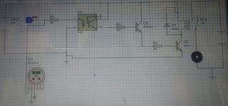
A 3-way solenoid valve and a
compressor were used, both at 12 volts, to manage the pulse from Arduino a
power circuit was implemented shown in figure 6, it uses an opto-coupler, a
bjt transistor and a tip 31 that connects to a 12v relay to operate the
components.
Figure 6. Power circuit
The project also made use of a
mpx5700 pressure sensor and from its formula found in the datasheet found the
corresponding pressure delivered by the compressor and delivered through the
solenoid valve when the inspiration and expiration of the system was performed
.
 The operation that can be
observed in the video, corresponds to a test to blow a lung (represented by a
blue elastic pump), through one way of the compressor and the other way was
directed to the pressure sensor, the compressor all the time was on to send a
constant flow and the change of I: E was achieved with help of the solenoid
valve.
CONCLUSIONS
It is possible to conclude that for the design of a mechanical ventilator we must differentiate nuy well which are the control modes to be used; In addition the alarms must be raised very well since these must be visible and audible to the person who is using the equipment. In the part of acquisition of the signal emitted by the sensor one must keep in mind its linearization and the equation that allows us to graph our ventilatory mode that is contained in the Datasheet of the sensor used.


No hay comentarios.:
Publicar un comentario